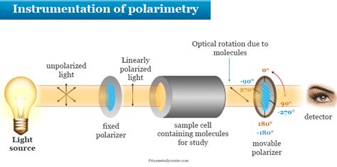
polarimeter block diagram|how to calculate polarimeter : importer Schematic diagram of a polarimeter. Previous slide: Next slide: Back to first slide: View graphic version
web26 de out. de 2022 · Så, när du spelar på ett casino utan svensk licens som ligger utanför eu ees så kan du behöva betala skatt på dina vinster. Betalningsmetoder om du ska spela med 10€ En annan fördel med att spela på utländska casino 10 euro är att de ofta erbjuder ett större urval av betalningsmetoder. De vanligaste du kommer att se är:
{plog:ftitle_list}
webPrefeitura Municipal de Nova Lima. Município de Nova Lima. CNPJ: 22.934.889/0001-17. Praça Bernardino de Lima, 80 - Nova Lima, MG. CEP: 34.000-279 | Telefone: (31) 3180-5760. Início. Prefeito e Vice Secretarias Telefones úteis História Símbolos Hino Ex-prefeitos Serviços Leis Municipais Publicações Oficiais Transparência Ouvidoria.
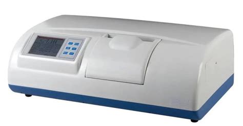
Schematic diagram of a polarimeter.A polarimeter is a scientific instrument used to measure optical rotation: the angle of rotation caused by passing linearly polarized light through an optically active substance. Some chemical substances are optically active, and linearly polarized (uni-directional) light will rotate either to the left (counter-clockwise) or right (clockw.A polarimeter refers to an optical instrument used to determine the polarization properties of light beams and samples. It consists of a polarization generator and analyzer, which produce and .
The schematic diagram of a typical polarimeter is a useful tool for anyone working with light-based experiments. It provides a clear visual representation of how a polarimeter .
types of polarometers
Figure 1 shows a functional block diagram of the polarimeter. The polarimeter has five sections: the laser source, the polarizing optics, the sample, the analyzing optics, and the detector. The .Schematic diagram of a polarimeter. Previous slide: Next slide: Back to first slide: View graphic versionBlock diagram of a simple polarimeter. Monochromatic light from the source is linearly polarized by the initial polarizer, and then allowed to pass through the sample medium. The angle of .The 4x4 Mueller matrix (MM) has been proven to be a powerful approach for understanding the whole optical properties of any sample. It is based on the analysis of the transformed polarization .
Fig. 12.1: Schematic Diagram of Polarimeter representing its components. 12.2 Principle. Polarimetry is based on the fact that when a polarized light passes through the sample tube .A polarimeter is an optical instrument with which one can accurately measure the angle by which the polarization of light is rotated e.g. when it passes through an optically active medium (containing chiral molecules).
Download scientific diagram | Block diagram of Kerr microscope/polarimeter describing the optical configuration and principal optical components. The polarimeter is shown in a single beam .Download scientific diagram | Block diagram of a general complete MM polarimeter using (a) two PEMs and (b) four PEMs with a single detection coupled with an electronic synchronization. The output .
TGI polarimeter block diagram for one pixel is shown in Figure 1, which shows a cold stage module inside a cryostat (20 K) and a Back-End module at room temperature (298 K).The cryogenic part is .Figure 1 shows a simplified block diagram of the polarimeter. Each receiver of the polarimeter has four NIR output signals that are modulated by means of a microwave phase-switching module. .
The spectrophotometer is an instrument which measures an amount of light that a sample absorbs. It works by passing a light beam through a sample to measure the light intensity of a sample. The polarimeter is released here as open hardware, with technical diagrams, a full parts list, and source code for its firmware included as Supplementary Information.No headers. Most research grade instruments found in academic and industrial labs are double beam instruments. An important advantage of a double-beam spectrophotometer over a single-beam spectrophotometer is that a double beam instrument permits compensation for source power fluctuations greatly improving S/N and extension to dilute solution samples and .
A polarimeter is an optical instrument with which one can accurately measure the angle by which the polarization of light is rotated e.g. when it passes through an optically active medium (containing chiral molecules). Operation Principle of Polarimeters. The basic operation principle of a polarimeter comprises the following:
Study Notes. A polarizer is a device through which only light waves oscillating in a single plane may pass. A polarimeter is an instrument used to determine the angle through which plane-polarized light has been rotated by a given sample. You will have the opportunity to use a polarimeter in the laboratory component of the course. An analyzer is the component of a .Schematic diagram of a polarimeter. Previous slide: Next slide: Back to first slide: View graphic versionFig. 12.1: Schematic Diagram of Polarimeter representing its components 12.2 Principle Polarimetry is based on the fact that when a polarized light passes through the sample tube containing optically active substance it exhibits angular rotation to the left (-) or right (+). Measurement of this rotation gives the optical rotation of the substance.
Fig. 1. Polarimeter block diagram. The Mueller matrix of the sample is determined from the modulated intensity measured by the detector. The two wave plates are rotated at different but harmonic rates, and a modulation of the detected intensity .Figure 1 shows a simplified block diagram of the polarimeter. Each receiver of the polarimeter has four NIR output signals that are modulated by means of a microwave phase-switching module. .These include the AGS polarimeter, the pC polarimeter in RHIC and the polarized H-jet target, also in RHIC. In addition to providing polarization measurements that are essential to the RHIC Spin Program, the polarimeters also make it possible to measure single and double spin asymmetries in the √s regimes accessible at RHIC.Download scientific diagram | Block diagram of a division of focal plane polarimeter. An array of pixel pitch-matched polarization filters are deposited on the surface of a CMOS or CCD imaging .
Download scientific diagram | Block diagram of the 100kHz-Mueller polarimeter in reflection. SS : Swept Source, DAQ: Data Acquisition board, PSG : Polarization State Generator, PSA : Polarization .
An example block diagram, showing the Microsoft Windows 2000 operating system architecture.. A block diagram is a diagram of a system in which the principal parts or functions are represented by blocks connected by lines that .

Download scientific diagram | Simplified block diagram of the two microwave polarimeter for N receivers with nearinfrared (1550 nm) correlation. (a) Microwave polarimeter previously proposed and .Flowchart Maker and Online Diagram Software. draw.io is free online diagram software. You can use it as a flowchart maker, network diagram software, to create UML online, as an ER diagram tool, to design database schema, to build BPMN online, as a circuit diagram maker, and more. draw.io can import .vsdx, Gliffy™ and Lucidchart™ files .Block diagram of the transmission experiment. The tunable laser and polarimeter were used to measure the PMD of the channel independently of the monitor (DGE is a dynamic gain equalizer, and WSS .
iphone 6 drop test with screen protector
iphone 6 drop test with tempered glass
A block diagram is especially useful for visualizing the inputs and outputs of your system, while what happens inbetween can remain in a black box. Block Diagram Examples and Templates. SmartDraw comes with a number of built-in block diagram templates as well as other circuit and wiring diagram examples to help you get started.The Advanced Stokes Polarimeter (ASP) converts a Stokes vector incident upon the Vacuum Tower Telescope (VTT) into a detected vector of recorded digital values. Fig. 1 Polarimeter block diagram Assuming linear response, this system can be described by si = XCTsp + b. (1) where si(x,y,A,t) measured instrument vector,
Block diagram for implementing a general Mueller matrix (MM )polarimeter into a scanning laser microscopy (SLM) architecture (a) in transmission and (b) in confocal reflection configuration.
A Polarimeter is a device for studying a transparent sample between crossed polarizing devices. Jean-Baptiste Biot (1774-1862) developed the polarimeter at the right, which was made by Soliel/Duboscq of Paris ca. 1850. The polarizer on the right-hand side uses a single plate of glass, while the analyzer on the left uses a pile of glass plates. . Block diagram of the Milan Polarimeter. The front end (dotted upper box) is cooled to 20 K and includes: the iris polarizer (Pol), the orthomode transducer (OMT), isolators (IS) and low noise HEMT amplifiers (He). A noise source (NS) provides via a power divider (PD) two coherent calibration signals which are injected into the system through .
Block diagram of the dynamic polarimeter alignment in transmission mode. As illustrated in Figure 2, the light source module is oriented at 30° in the PSA and photodetector directions in reflection mode. This configuration setup uses a front surface mirror as a reference sample. Like transmission mode, 36 measurements are automatically .Download scientific diagram | Block diagram of the polarimeter from publication: The polarimetric observation facility at the Medicina 32 m parabolic antenna | We describe the wideband analog .
polarometer schematic diagram
polarimetry diagram pdf

webPlace bets on In-Play Darts matches and catch up with the latest scores live. Darts .
polarimeter block diagram|how to calculate polarimeter