measuring rod bearing thickness|crankshaft bearing thickness chart : Brand manufacturer Main Bearings - Line Bore Measurement: A factory stock engine case for a 1200cc 40 horse single port, a single port 1300, 1500 or 1600cc or a dual port 1600cc engine has a line bore ID of 65mm or 2.560”. . Rod bearing . webPorto Seguro - BA Reservas: 0800 771 1514
[email protected] O Portobello Park oferece opções incríveis! Piscinas, playground, tobogã, futebol, quadra, parquinho, .
{plog:ftitle_list}
WEBNote: Follow all your favorite sports on Livesport.com! On Livesport.com homepage you will find today's scores from the top events across all sports. You can click on any sport .
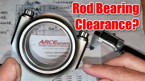
To measure the wall thickness of a main or rod bearing correctly the location on the bearing that you measure and the tool you use will determine the level of accuracy of the measurement. A micrometer with a ball anvil must be used to fit the curvature of the bearing . This article explains what tools and techniques you need to properly measure engine rod bearing clearance.PLASTIGAUGE® is the world standard in Plastic Precision Clearance Gauges for the measurement of clearance between fitted surfaces. Plastigauge is extremely effective for measuring the clearance of a wide variety of bearings which . To measure the wall thickness of a main or rod bearing correctly the location on the bearing that you measure and the tool you use will determine the level of accuracy of the measurement. A micrometer with a ball anvil must .
Main Bearings - Line Bore Measurement: A factory stock engine case for a 1200cc 40 horse single port, a single port 1300, 1500 or 1600cc or a dual port 1600cc engine has a line bore ID of 65mm or 2.560”. . Rod bearing . Setting bearing clearance for a performance engine is a fundamental step in the building process. There are no quick and easy ways to establish this critical.
Plastigauge is a great product for checking bearing clearance in your engine or any place where measuring a hidden clearance is required. . It is comprised of a rod or thread of a compliant plastic material of accurately determined cross-section - either circular or square. The surfaces between which measurement is to be made are first .It has a lemon shape due to the varying thickness of the bearing wall having maximal value at the centerline (T) and gradually decreasing towards the parting line. It is accepted to measure the minimal value of the bearing wall thickness (Te) at a certain specified height h (Fig.2) in order to exclude the zone of the crush relief.differ slightly in thickness within allowed tolerance limits. For these reasons, bearing clearances are specified as “vertical clearance” and must be measured at 90 degrees to the split line. The best method of measurement is with a dial bore gage that measures the bearing inside iameter when the bearings are installed at theMeasurement of the main dimensions of the bearing. ①Bearing thickness: The fixed probe of the outer micrometer changes from a flat surface to a spherical surface, which can be used to measure the thickness of the bearing. The thickness of the approach path should generally be controlled within the range of 0.005~0.010mm.
To properly calculate your aftermarket bearing clearance, you must measure the inside diameter of your bearing tunnel or housing bore, and subtract that from the outside diameter of the crank journal, finally double the bearing thickness to achieve the clearance value. . Rod bearing thickness by color . After cleaning the oil from the bearing surfaces to make for an accurate measurement Eric breaks off a journal-width piece of the green plastic filament and places it across the journal. Reinstalling the bearing and cap he proceeds to torque the rod bolts to the specified amount. This action smashes the Plastigage filament, spreading it out.Remember, always measure bearing wall thickness at the bearing centerline (90 degrees from the parting lines). Measuring at the parting line, will likely result in . Typically, connecting rod bore displacement due to crush is about .0005”; main and cam bearing bore displacements are about .0003”. TheThis paper presents an experimental method to measure the thickness of oil film of a connecting-rod big end bearing. A specific experimental device and a connecting-rod model of photo-elastic material are used to determine the load diagram and to measure the oil film thickness. The method consists in taking two images of a solid, before and after deformation. .
the thickness of the bearing steel back. The effect of bearing thickness on contact pressure is shown in Fig.6. The required minimum value of 1500 psi pressure in a steel housing is achieved with a bearing whose steel back is thicker than 0.04”, whereas the bearing back thickness in an
rod bearing thickness chart

rod bearing clearance measurement
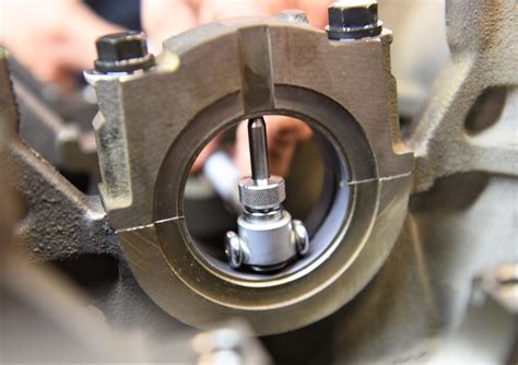
BT = bearing thickness Main Bearing thickness by color . I´m building a K24a4 block and ordered PPA rod bearings to test clearence with. Now the Pink PPA bearing seems to be out of stock in Europe and I have to wait till beginning of June. Does RBB rod bearing fit as direct replacement. Same color is same dimension for both RBB and PPA? If measuring the bearing wall thickness, use a special micrometer with a ball anvil to fit the curvature of the bearing ID. The best way to determine bearing clearance is to measure the bearing ID with the bearings installed .

If measuring the bearing wall thickness, use a special micrometer with a ball anvil to fit the curvature of the bearing ID. . .0005" difference in wall size; b) and always install the thickest wall shell in the upper position if installing a rod .
the question of measuring wall thickness of the bearings to calculate the clearances still comes up from time to time. To measure the wall thickness of a main or rod bearing correctly the location on the bearing that you measure and the tool you use will determine the level of accuracy of the measurement. The focus of this study was to accurately measure the oil film thickness across the width of a connecting rod bearing operating under load. A new experimental method using Laser Induced . The purpose of this study is to investigate the application of non-destructive testing methods in measuring bearing oil film thickness to ensure that bearings are in a normal lubrication state. The oil film thickness is a crucial parameter reflecting the lubrication status of bearings, directly influencing the operational state of bearing .
Four eddy current gap sensors for each bearing are used to measure the oil-film thickness and to deduce the bearing trajectories. Experimental data for crankshaft main bearings are easy to obtain but connecting-rod bearings are more difficult to control due to the difficulty of installing instrumentation on connecting-rods that are rotating and . A runout of more than 0.005”(0.125 mm) at the bearing flange cannot be corrected by the use of a shim. The combination of the rotor and bearing flange could prevent the rotor from being turned. Check the bearing flange runout after friction surface runout. Check flange runout by changing the rotor position 180º on the bearing. One for main journals and other for rod journals. For rod journals the letter is in the crank and number on the rod. For main journals the number is on the crank and letters on the casing. If your rod journals are all B you just have to check the number on the rod. If all of them are 1 they would all be B1. Which is the D bearing (green).
After measuring all eight rod bearing clearances and using shell halves to set the clearances, it’s very common to have a clearance spread between the rods of perhaps 0.0004- to 0.0005-inch. Let’s say our loosest rod bearing measured 0.0028-inch while the tightest rod came in at 0.0023-inch – creating a spread of 0.0005-inch. Connecting rod bearing failure can have catastrophic effects, potentially causing the connecting rod to snap (known colloquially as” throwing a rod”) and driving it through the crankcase, thereby destroying the engine. . (TCM) enable the measurement of bearing film thickness within real systems. As its name suggests, TCM measures the . In a running engine, cylinder pressure pushes downward on the piston, reducing that 0.001-inch figure. A loaded connecting rod at peak cylinder pressure will reduce that oil film clearance to as small as 0.0002-inch. With a static bearing clearance of 0.002-inch that means the upper half of the rod bearing has 0.0198-inch worth of clearance.
Then they stamp the number into the crankcase so that the bearings can be replaced without re-measuring the clearances. So to kind of answer your question, I'm assuming that using the original color bearings will get you the correct bearing clearances as indicated in the manual. The only way to know for sure is to measure, or plastigage.To measure the outside diameter of a bearing place the jaws of the caliper around the bearing and close it until its a good fit but not tight, now read the value from the caliper. In the same manner as you measured the outside diameter measure the width as shown.

rod bearing clearance check

hard drive test tool usb
web707 Followers, 655 Following, 115 Posts - See Instagram photos and videos from Rafaela Gambin (@rafaelagambin)
measuring rod bearing thickness|crankshaft bearing thickness chart