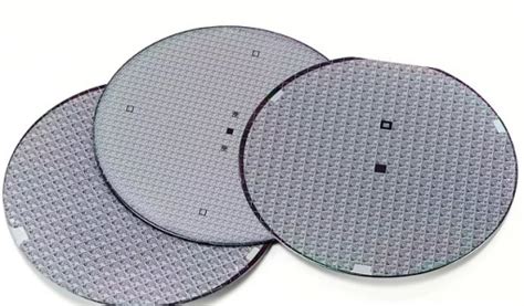
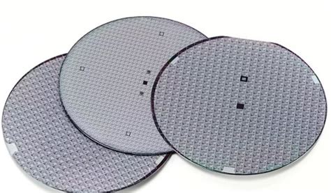
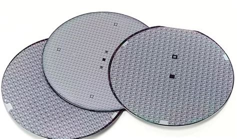
measurements wafer thickness|willrich wafer thickness : exporters THICKNESS MEASUREMENT. ASTM F657: The distance through a wafer between corresponding points on the front and back surface. Thickness is expressed in microns or . Resultado da TEX WILLER. Owner hidden. . Apr 24, 2020 — Download. Files. Asterix Volume 32 Asterix Tra Banchi E Banchetti Fumetti muj - Sconosciuto .
{plog:ftitle_list}
Check chromabets.com with our free review tool and find out if chromabets.com is legit and reliable. Need advice? Report scams Check Scamadviser!
Use a three-point method to define a reference plane on the outer edges of the wafer. This plane serves as your baseline. 2. Measure the Center Point. Determine the height of the median surface at the center of the wafer. .THICKNESS MEASUREMENT. ASTM F657: The distance through a wafer between corresponding points on the front and back surface. Thickness is expressed in microns or .
Another limitation is the possibility that the thickness of the electrically conducting layer may differ from the metallurgical thickness [6]. 4-pp can be used in a true mapping mode to measure several tens of points per wafer, as each point takes only a few seconds (Figure 15.2).

Measuring wafer bow and warp doesn’t have to be complicated if you stick to a clear process: Prepare the Wafer: Start with a clean, contaminant-free surface.; Choose a Measurement Tool: Pick the right tool for bow, warp, .The Proforma 300iSA is a benchtop/desktop, semi-automated wafer measurement system for semi-conducting and semi-insulating materials delivering full wafer surface scanning for thickness, thickness variation, .
These non-contact systems provide highly precise measurements of semiconducting and semi-insulating wafers up to 20k Ohm-cm. Proforma technology has a wide wafer thickness measurement range and provides excellent repeatability. It is ideal for measurements of Silicon and other semiconductor materials. Capacitance sensing can be used to measure .In the wafer grinding back-end process, thinning the wafer is essential to enhance device performance and minimize heat dissipation. Precision in this thinning process is achieved through methods like mechanical grinding or chemical mechanical polishing (CMP), where accurate thickness measurement tools such as stylus profilers or optical sensors play a crucial role.
willrich wafer thinning
height between the wafer’s top surface and the chuck table and therefore the wafer thickness. This is the solu-tion of choice for difficult-to-measure wafers. An inno-vative algorithm featuring quantile filters for measure-ments on rough surfaces ensures stable and accurate measurement results. The Precitec wafer step-height

Filmetrics ® offers tabletop, mapping, and production systems for wafer thickness measurement and membrane thickness measurement. Wafer materials commonly measured include single polished or double polished Si (Silicon), Sapphire, Fused Silica, SiC, Li TaO3, GaN, and Glass.SemDex M2 contains multiple optical measuring instruments to measure geometric dimensions of wafers, microchips, as long as they are part of the wafer. The metrology tool also evaluates sub-structures of a microchip either if they are manufactured in front-end-of-line (FEOL), back-end-of-line (BEOL) or in Advanced Packaging processes.
In the wafer grinding back-end process, thinning the wafer is essential to enhance device performance and minimize heat dissipation. Precision in this thinning process is achieved through methods like mechanical grinding or chemical mechanical polishing (CMP), where accurate thickness measurement tools such as stylus profilers or optical sensors play a crucial role.
The size of wafers for photovoltaics is 100–200 mm square and the thickness is 100–500 μm. [10] Electronics use wafer sizes from 100 to 450 mm diameter. The largest wafers made have a diameter of 450 mm, [11] but are not yet in general use.
willrich wafer thickness
PDF | On Jan 1, 2008, Andy Robinson and others published Overview of tomography techniques to measure wafer thickness in MEMS structures | Find, read and cite all the research you need on ResearchGate
The MPT1000 is Chapman Instruments’ latest non-contact system, providing wafer thickness measurements. It can be used as a production tool for in-line quality inspection, a research and development tool for establishing standards, and compiling data for enhancing productivity. The MPT1000 utilizes a sophisticated non-contact measurement technology with a focused laser .In-process thickness monitoring during wafer thinning and structuring. As the demand for wafers with ever-lower total thickness variation (TTV) or defined structured surface is increasing, extremely accurate in-process thickness monitoring through non-contact, non-destructive measurement technology is becoming indispensable.
mirror, 120mm scans for a 150mm wafer. Figure 3. Measurements of a mirror with a certified radius of 20.13 ± 0.5m. Stress Measurement Resolution Stress resolution is dependent on three parameters: the . thickness are on the order of hundreds of microns, while film thickness will typically vary between 100Å a nd 2µm, and thereThe interaction of the wafer, slurry and pad determines the material removal rate during Chemical Mechanical Planarization (CMP). Dual emission laser induced fluorescence (DELIF) provides a means to measure the slurry layer thickness between the wafer and a Fruedenbergy FX9 pad during CMP with high spatial (4.3 mm/pixel) and temporal resolution (2 Hz).
%PDF-1.7 %äãÏÒ 2 0 obj > stream xœ¥[IsÛÈ’¾ëWp"æ¾ aTao_Æ‹Ü£ Ûíhéõ‹ Û €H´A€ Ej½ÃüöÉ¥²Pòòfìƒ2 µfåòeUñåÍų7ÁJnn/Tì .When configured as a Dual Probe system, the FSM413 also provides measure- ments of the total thickness of the wafer, including substrate thickness and the patterned height thickness in cases the beam cannot penetrate through the .
Terahertz thickness measurements are conducted on high resistive silicon wafers of 2-, 3.5-, 4-, and 8- mm thickness and 2 inch diameter. For this, a frequency sweep is performed over the two frequency regions for each sample with an additional reference measurement without sample. Next, an optical metrology technique, in particular the moiré technique with the Talbot effect, is described for measuring wafer surface with a non-contact whole-wafer optical method. Phase-shifting technology is introduced to enhance the resolution of the optical moiré technique for wafer surface measurement.between several measurements has an average over all pixels of about 3nm rms. An important limitation of IR3 for wafer thickness variation measurements must be mentioned. Wafers with higher doping levels are not transparent at 1552nm and a different thickness variation metrology is required to pre-pare such wafers for sub-aperture finishing .and for wafer thickness measurement (with refractive index ~3.82) 50 µm to 1.05 mm. With multi-layer thickness measurements of silicon wafers, up to 5 layers from 50 to 1050 µm can be detected. ø 10 mm TH24 Nanometer-accurate thickness measurement from 0.05 to 1.05 mm Undoped, doped and highly doped wafers Multi-peak: up to 5 layers
willrich precision wafer thinning
Wafer bonding and thinning processes in three-dimensional Si–Si bonding technology may cause the nonuniform thickness of the Si thin film. This in turn will lead to nonuniform thermal conductivity (TC) as phonon boundary scattering dominates TC at the submicron scale. The simultaneous scanning thickness and TC of the Si thin film are . In this work, a measurement device is described that measures thickness variation of double side polished wafers using an infrared source and vidicon detector. Various possible instrument configurations are described with the focus on a setup which uses a collimated wavefront to produce interference fringes between the front and back surfaces .

These sensors are mainly used to determine wafer thicknesses very precisely. But it is also possible to characterize single layers of multi-layer systems. Measurement of Bond Layer Thickness. Measurement of Wafer thickness and Membrane thickness. The newest generation of FormFactor FRT IRT 800 sensor offers major advantages: The most common deviations are total thickness variation (TTV), bow, and warp. Their definitions are shown in Fig. 36.1.These and other shape parameters are defined in the SEMI International Standards, which also give detailed instructions on measurements [3]. Nonidealities in wafer shape can affect the capability of device processing steps, including .Measurement: Wafers are placed in the measurement system, and various parameters such as thickness, diameter, and surface characteristics are measured using appropriate techniques. iv). Analysis: Measurement data is analyzed to assess the quality and suitability of wafers for semiconductor manufacturing processes.Wafer Thickness Measurement. Ultra High-accuracy Reliable Measurement with Spectral interferometry SI-F series. View Catalog; Ultra High Resolution 1nm. Spectral Interference Method that enables 1 nm Resolution. Head Variations That Expand the Range of Possible Measurements.
polarimeter kruss p3000
polarimeter lab manual
WEBAtendimento. Educação. Saúde. Conteúdo. Utilidades. Fale com a Oi. Confira a lista de telefones de outras centrais de atendimento Oi. Dúvidas sobre Educa +. Enviar .
measurements wafer thickness|willrich wafer thickness